Ah, some news.
have just spoken to Rick at Cubic performance, he says that the bezels screw on and off so are easy to remove and change. Looks like I may have found my answer. They also come without the Kirkham logo!
Thursday 27 November 2008
Still planning!
Well you know I said that I could change my mind on things rather a lot, well I think I might have done it again!
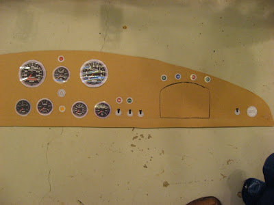
Back to dash layout and gauges.
After Simon very kindly sent me a Turin shroud dash, I was able to transfer the layout onto a bit of MDF.
I then set about making some rather fetching gauges, indicator lights and switches using Autometer pictures and powerpoint drawing tool! End result a life size dash and hardware that I can fiddle around with as I like.
Now Autometer sell two sizes of speedo and tach, one at 127mm and one at 85ish. Anyway one is smaller than normal UK sourced gauges and one bigger.
Heres the small ones.
And the large ones.
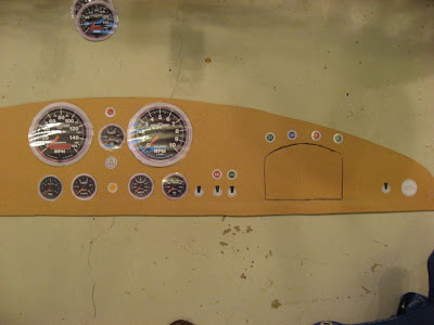
Upshot, don't think I like either! And I need to paint the floor again!!
So the hunt continues for full sweep electrical gauges that I like with decent through the dial lighting.
Enter Kirkham http://www.thomaskirkham.com/gauges.html
 Now these I like, classic design, full electric transducers and good through dial lighting, oh and °C temperature measurements. Just need to find out if its possible to change the bezel to something a little more IVA (note the change there from SVA) friendly.
Back to dash layout and gauges.
After Simon very kindly sent me a Turin shroud dash, I was able to transfer the layout onto a bit of MDF.
I then set about making some rather fetching gauges, indicator lights and switches using Autometer pictures and powerpoint drawing tool! End result a life size dash and hardware that I can fiddle around with as I like.
Now Autometer sell two sizes of speedo and tach, one at 127mm and one at 85ish. Anyway one is smaller than normal UK sourced gauges and one bigger.
Heres the small ones.

And the large ones.

Upshot, don't think I like either! And I need to paint the floor again!!
So the hunt continues for full sweep electrical gauges that I like with decent through the dial lighting.
Enter Kirkham http://www.thomaskirkham.com/gauges.html
 Now these I like, classic design, full electric transducers and good through dial lighting, oh and °C temperature measurements. Just need to find out if its possible to change the bezel to something a little more IVA (note the change there from SVA) friendly.
Saturday 4 October 2008
Back to Electrics...
Some time ago I posted up regarding the Isquared 1+1 system designed to make wiring easier by replacing masses of cabling. Well at the time I mentioned that the system was due to be upgraded to the ISIS system. Finally the first units have been shipped out and the ISIS website www.isispower.com is up and running.
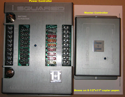
Here is a pic of the 2 Powercell system from the user manual followed by a close up of the first units delivered to a Factory Five Cobra builder in the US. The close up system also has the optional RF link module (remote) and LCD diag display fitted.
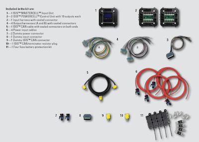
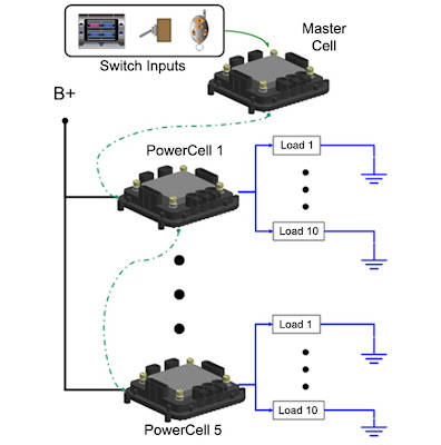
 This really is the next step up, all that is required is to run a CAN cable and main power cable from front to back of the car. All functions are controlled via CAN messages and as such the system can be programmed to respond how you want.
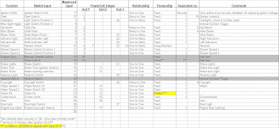
All trigger switching is at low voltage, 5v, signal level to ground. So each dash switch will have ground connected to one side and its output into the Mastercell. Given that GD switch full system current through the ignition switch this is something I am much happier with. Im sure the Vauxhall ignition switch can cope but not having high current floating around my dash is something I like much more.
More details to follow after Ive been to the post office. Nothing to do with this, just need to get there before they close!
Right, parcel posted.
Each input can relate to one or more outputs and conversely many inputs can control one output. So for instance if the fog light must only come on when the side lights are on you just set a relationship such that both input must be on for the output to be active.
This is set up using characteristic's called relationships and personalities;
Relationship describes how the input put relates to the output for example One to One for one input to one output or on to many for 2 inputs required to trigger one output.
Personalities describe how the output functions. Track for instance follows the input state whilst toggle changes state for each change of input state (momentary input switch gives latching output)
Slowly I've gone through and mapped out all the circuits I can think of and decided how to connect them up, how they should function and assigned personalities and relationships. Boy do I know how to have fun!
 I figure on 3 Powercells to sort the GD, I know its going to be more expensive than buying the GD looms but on the upside its more fun, a bit more modern and hopefully easier. Also I figured the GD is a modern interpretation of a classic brought up to date, why leave the wiring in the 1960's?
This will give some other advantages as well;
1) The ability to turn on any circuit I want from the remote key fob. (lights for example to help find the car in a row of others)
2) Timed functions such as rad fans that can remain powered for a period after ignition off.
3) Ignition and starter circuit will be disabled until the key fob is pressed or similar security feature enabled.
Another thing as well, if I decide that I dont ike the programming, it can be change in situ so a switch function can be re assigned without taking anything apart.
Im liking this the more I look at it, at least Ive figured it out now before buying any looms.
Here is a pic of the 2 Powercell system from the user manual followed by a close up of the first units delivered to a Factory Five Cobra builder in the US. The close up system also has the optional RF link module (remote) and LCD diag display fitted.

 This really is the next step up, all that is required is to run a CAN cable and main power cable from front to back of the car. All functions are controlled via CAN messages and as such the system can be programmed to respond how you want.
All trigger switching is at low voltage, 5v, signal level to ground. So each dash switch will have ground connected to one side and its output into the Mastercell. Given that GD switch full system current through the ignition switch this is something I am much happier with. Im sure the Vauxhall ignition switch can cope but not having high current floating around my dash is something I like much more.
More details to follow after Ive been to the post office. Nothing to do with this, just need to get there before they close!
Right, parcel posted.
Each input can relate to one or more outputs and conversely many inputs can control one output. So for instance if the fog light must only come on when the side lights are on you just set a relationship such that both input must be on for the output to be active.
This is set up using characteristic's called relationships and personalities;
Relationship describes how the input put relates to the output for example One to One for one input to one output or on to many for 2 inputs required to trigger one output.
Personalities describe how the output functions. Track for instance follows the input state whilst toggle changes state for each change of input state (momentary input switch gives latching output)
Slowly I've gone through and mapped out all the circuits I can think of and decided how to connect them up, how they should function and assigned personalities and relationships. Boy do I know how to have fun!
 I figure on 3 Powercells to sort the GD, I know its going to be more expensive than buying the GD looms but on the upside its more fun, a bit more modern and hopefully easier. Also I figured the GD is a modern interpretation of a classic brought up to date, why leave the wiring in the 1960's?
This will give some other advantages as well;
1) The ability to turn on any circuit I want from the remote key fob. (lights for example to help find the car in a row of others)
2) Timed functions such as rad fans that can remain powered for a period after ignition off.
3) Ignition and starter circuit will be disabled until the key fob is pressed or similar security feature enabled.
Another thing as well, if I decide that I dont ike the programming, it can be change in situ so a switch function can be re assigned without taking anything apart.
Im liking this the more I look at it, at least Ive figured it out now before buying any looms.
Saturday 27 September 2008
Tranmission selection.
Don't get too excited, there's still limited possibility of actually being able to get things moving again, however I thought I would document the choice of transmission.
Like most I've opted for the Tremec TKO box.
 With this I have a choice of torque capabilities and 5th gear ratio.
To help decide which one to go for I put each option into excel and a little motormath program I found on the internet.


 With the wheel and tyres sizes from GD and the 3.07 diff I have I was able to figure out the following results.
 So I settled on the TKO 600 with the 0.82 5th, a chat with Andy at GD confirmed my choice as a good one. I should be able to cruise nicely but be in a good position on the torque curve should I wish to get things moving without constantly having to mash the gears.
I will be sourcing the complete kit, minus flywheel and bolts, from Repower, spoke to them and found out that the only draw back is that prices on Tremec missions is increasing due to raw material price rises. Looks like I've got to budget a bit more now, never mind.
One thing I have decided is I must have a smooth aluminium shift knob, my Type R has one and it feels really nice in the palm of you hand, strange but true!
Wednesday 6 August 2008

Tuesday 22 July 2008
Slow going..
Apologies for lack of updates, this is directly proportional to the progress made in the garage.
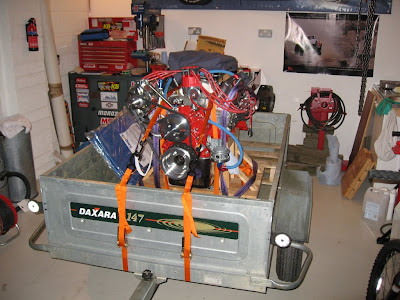
Since my last post I have now sealed the sump on hopefully for the last time and set the engine down in its cradle. Not a great deal of point adding a picture of that!
So next step is to prep it for storage as its going to be a quite a while before I can stretch to a gearbox and bell housing. (thats another story which I may tell one day).
To lay it up Ive purchased many litres of oil (35!) and a bottle of Engine Guard vapour inhibitor. The plan is to fill the engine pretty much up with oil and then add the Engine Guard to protect the bits not submersed in oil.
So that's going to be it for a while I'm afraid, at least Im not having to sell it, yet.
Sunday 1 June 2008
Leak Repair 2.
OK, so on to leak repair No.2, the rear main seal.
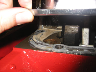
With oil confirmed as leaking out of the rear main seal there was nothing for it other than taking it apart again. The sump came off with a little more resistances this time telling me that Id made a good seal last time.
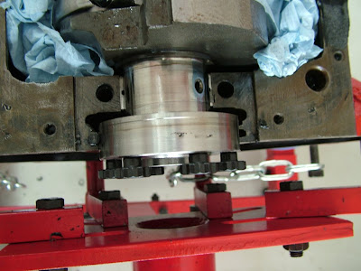 The main cap was removed and seal inspected, nothing immediately showed up and the crank looked in good nick. I did notice some black crud on the crank, but wasn't sure what it was at that stage.
Reviewing the photo I took showed that the flag on the seal was stressed and had started to break up, I also perceived I saw something on the actual sealing lip.
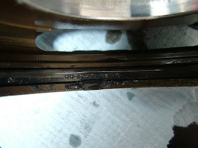
Removing the block side seal gave further clues, the flag was missing.
Using a feeler gauge I cleared out whatever was between the crank and block, basically bits of melted seal flag. Some of the bits had been engine side so had obviously travelled over the seal lip.
The crank was cleaned and a new seal fitted, this time with the flags removed! Seal clocked to separate block/cap join and seal join and a small dab of silicone on the block before the cap went down.
Job done, now to scrap off all the old sealant ready for sump install No. 3!!
With oil confirmed as leaking out of the rear main seal there was nothing for it other than taking it apart again. The sump came off with a little more resistances this time telling me that Id made a good seal last time.
 The main cap was removed and seal inspected, nothing immediately showed up and the crank looked in good nick. I did notice some black crud on the crank, but wasn't sure what it was at that stage.
Reviewing the photo I took showed that the flag on the seal was stressed and had started to break up, I also perceived I saw something on the actual sealing lip.

Removing the block side seal gave further clues, the flag was missing.

Using a feeler gauge I cleared out whatever was between the crank and block, basically bits of melted seal flag. Some of the bits had been engine side so had obviously travelled over the seal lip.
The crank was cleaned and a new seal fitted, this time with the flags removed! Seal clocked to separate block/cap join and seal join and a small dab of silicone on the block before the cap went down.

Job done, now to scrap off all the old sealant ready for sump install No. 3!!
Saturday 31 May 2008
2nd Dyno Day.
Tim very kindly offered to put the motor back on the dyno to run out the water from the engine. So this time father in law accompanied me on the trip to Market Drayton.
All went well this time, fired up straight away again and started to steam as it ran, but this time no more water entered the oil and it gradually cleaned out. Each check of the stick showed less water and clean oil, great news.
Also picked up a few more horses and torques on the way making 336bhp and 330 ft/lbs. Wahey!
However as always the good bad balance was restored when an oil leak started at the rear main seal area.
With the engine off it looked initially like the flywheel bolts might be to blame but after getting the motor home and filling it with oil to store it the leak was clearly evident. So this is why the next post will be called Leak repair 2. See I told I knew why the first one was called 1!!
Any how I did get some video of the engine on a run with me in the dyno cell, its in this short video I put together to show the family what I've been up to.
Enjoy..
Leak Repair 1.
It says Leak Repair 1 because I'm writing this retrospectively and know what's coming next!
Well I put the engine stand back up and set about finding out where the water leak came from, first off it was evident that the final run really mixed things up.
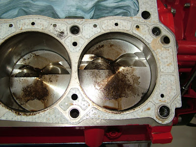
 Obvious candidate was the intake to head seals so off came the top end. All looked OK with no obvious path for water to have made it to my oil. Looking on www.Ford uscle.com I found others talking of oil leaks caused by poor head gaskets, and in particular the Mr Gasket's that I had used. The oil leak in question matched the slight leak which had developed on both heads during the dyno runs. So I travelled further down and removed the first head. What I found was not pretty, the entire deck surface was wet and there was obvious signs of combustion gasses leaking over the cylinder seals.

 It looks like the water had found its way under the gaskets and into the oil drain back holes, a slow leak at first which just got worse.
 So I purchased some nice new Fel Pro gaskets which just looked better, clear sealing material on both sides in all the right places.
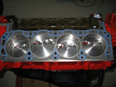 With those in place I set about cleaning the heads and intake of old silicone, what a job! Any way eventually it was all clean and I could re-assemble.
As well as the water leak my sump was leaking oil as well so that came off and what do you know, Mr Gasket had let me down again. This time the Ultraseal one piece gaskets just didn't do the job.
 So again new Fel Pro gaskets were used (thanks Tim) with plenty of sealant.
So it was all fixed and ready to be tested again.
Well I put the engine stand back up and set about finding out where the water leak came from, first off it was evident that the final run really mixed things up.
 Obvious candidate was the intake to head seals so off came the top end. All looked OK with no obvious path for water to have made it to my oil. Looking on www.Ford uscle.com I found others talking of oil leaks caused by poor head gaskets, and in particular the Mr Gasket's that I had used. The oil leak in question matched the slight leak which had developed on both heads during the dyno runs. So I travelled further down and removed the first head. What I found was not pretty, the entire deck surface was wet and there was obvious signs of combustion gasses leaking over the cylinder seals.
 It looks like the water had found its way under the gaskets and into the oil drain back holes, a slow leak at first which just got worse.
 So I purchased some nice new Fel Pro gaskets which just looked better, clear sealing material on both sides in all the right places.
 With those in place I set about cleaning the heads and intake of old silicone, what a job! Any way eventually it was all clean and I could re-assemble.
As well as the water leak my sump was leaking oil as well so that came off and what do you know, Mr Gasket had let me down again. This time the Ultraseal one piece gaskets just didn't do the job.
 So again new Fel Pro gaskets were used (thanks Tim) with plenty of sealant.
So it was all fixed and ready to be tested again.
Monday 28 April 2008
Andy goes to the dyno....
Well the day finally came to go to the dyno.
With the engine strapped firmly to my home made stand I hoisted it into the trailer and fitted my carefully engineered bits of pallet to jam it in place. A couple more ratchet straps to hold it down and with a bit of luck it wont go bouncing off down the road!
 I loaded all the other bits like starter, flywheel, ignition system and ari cleaner into the boot, strapped dad in the front seat and off we went.
After a fairly uneventfull 57 mph 2 hour trip up to Market Drayton we arrived and were met by Tim Adams.
During this build I have visited 4 key places, Henwick garage to buy the engine, John Gordons to buy the running gear, GD to buy the kit and now Tim to dyno the engine. The one thing that's common to all of them was the feeling you get when you walk in, they all felt right as if you could tell that they all knew what they were talking about before they said a word.
Anyway after a bit of a chat about business and what Tim does we unloaded the engine and headed for the dyno, and there it was like some macabre instrument of engine torture!
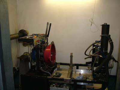 Tim set to work and after about an hours fiddling we were ready to go.
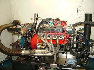
As you can see in the video I was astounded when it fired up on the third turn of the crank, Tim took it straight to 2,500 rpm and it sat there for 30 minutes breaking the cam in.
So we had water in the oil, not so good.
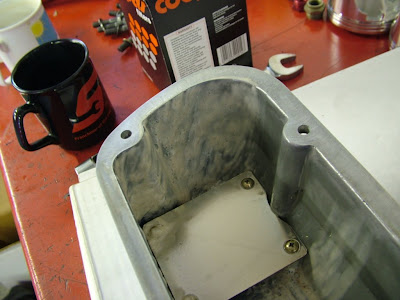 Mayonnaise with your lunch anyone?
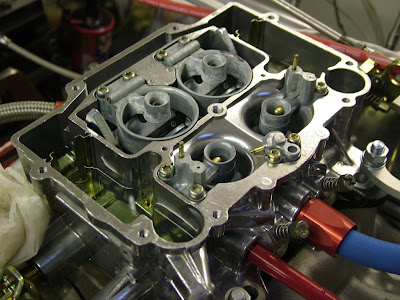
We cleaned the worst of it out at this stage thinking t could be condensation and pressed on to jet the carb, heres what one looks like without a lid!
With it jetted correctly Tim was happy with the figures he was seeing. We decided not to play with the timing anymore so I could run on regular unleaded.
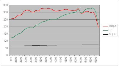 Still 331 BHP and 324 torque isnt going to slouch along!
Thanks goes to Tim for a great day out and all his help in trying to figure out what went wrong, taking the leak aside I am really happy with the way it fired up so easily and it idles nicely at 920 rpm. Tim says this is mostly due to Bassets Down's balancing work as its so smooth.
Now all I have to do is fix that leak!
With the engine strapped firmly to my home made stand I hoisted it into the trailer and fitted my carefully engineered bits of pallet to jam it in place. A couple more ratchet straps to hold it down and with a bit of luck it wont go bouncing off down the road!
 I loaded all the other bits like starter, flywheel, ignition system and ari cleaner into the boot, strapped dad in the front seat and off we went.
After a fairly uneventfull 57 mph 2 hour trip up to Market Drayton we arrived and were met by Tim Adams.
During this build I have visited 4 key places, Henwick garage to buy the engine, John Gordons to buy the running gear, GD to buy the kit and now Tim to dyno the engine. The one thing that's common to all of them was the feeling you get when you walk in, they all felt right as if you could tell that they all knew what they were talking about before they said a word.
Anyway after a bit of a chat about business and what Tim does we unloaded the engine and headed for the dyno, and there it was like some macabre instrument of engine torture!
 Tim set to work and after about an hours fiddling we were ready to go.
As you can see in the video I was astounded when it fired up on the third turn of the crank, Tim took it straight to 2,500 rpm and it sat there for 30 minutes breaking the cam in.
So we had water in the oil, not so good.
 Mayonnaise with your lunch anyone?
We cleaned the worst of it out at this stage thinking t could be condensation and pressed on to jet the carb, heres what one looks like without a lid!

With it jetted correctly Tim was happy with the figures he was seeing. We decided not to play with the timing anymore so I could run on regular unleaded.
 Still 331 BHP and 324 torque isnt going to slouch along!
Thanks goes to Tim for a great day out and all his help in trying to figure out what went wrong, taking the leak aside I am really happy with the way it fired up so easily and it idles nicely at 920 rpm. Tim says this is mostly due to Bassets Down's balancing work as its so smooth.
Now all I have to do is fix that leak!
Friday 25 April 2008
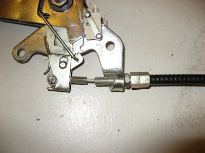
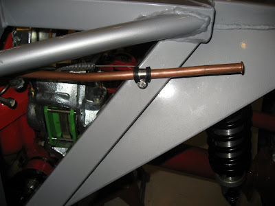
Handbrake fixed.
After receiving a replacement cable from GD I modified and fitted this one with much greater success. So I now have working handbrake which will be useful when moving the chassis outside as the driveway slopes away from the garage!
Monday 21 April 2008
Electrickery.
In the past I have seriously considered looking at the whole harness and wiring issue a little differently to what most people opt for.
The standard, and some might say tried and tested way, is to use relays to switch high current loads thus avoiding the need for high current capacity switches on the dashboard. In addition you will also find standard loom design requiring heavy capacity wires running from the relays to the front and rear of the vehicle to power the loads.
In the mass pro sector we use CAN bus, this system uses a messaging system from system ECU's to communicate with the central power distribution point so you no longer need a switch on the dash board that is capable of handling high currents. For example the heater control tells the heater fan to turn on using a message instead of actually switching the motor current in and out itself.
Anyway finally this type of technology has made it into the kit car world and the first unit which caught my eye was the Isquared 1+1 system on offer from www.isqe.com it does not appear to be what I would call a CAN system as it uses a single control module to a remote power distribution or smart fuse box. No relays here all switching via MOSFET's.
 These images have been copied from another build site I found on the net:
http://home.comcast.net/~289fia_cobra/index.htm
After emailing Chris at ISquared I am now informed of a newer system called ISIS manufactured by Littlefuse which works more along the true CAN idea of a master controller connected to multiple sub power modules.
Each power module can control up to 10 loads. With this system the harness going from the front to the back of the car could consist of just +12V, Ground, the CAN lines (usually 2 wires in a twisted pair format) and any sender lines you may have. This instead of the normal tree trunk harness.
So for a Cobra you would most likely need 1 master module in the front and one power module at the back. No relays again.

So that's got me thinking again. Obviously I need to understand prices of both systems but I am warming to the idea, certainly with the 1+1 system fault finding will be so much easier as you can tell if the switch is working by checking the function LED on the power module.
Again watch this space, I may well change my mind totally and stick with the old ways or maybe not.....
The standard, and some might say tried and tested way, is to use relays to switch high current loads thus avoiding the need for high current capacity switches on the dashboard. In addition you will also find standard loom design requiring heavy capacity wires running from the relays to the front and rear of the vehicle to power the loads.
In the mass pro sector we use CAN bus, this system uses a messaging system from system ECU's to communicate with the central power distribution point so you no longer need a switch on the dash board that is capable of handling high currents. For example the heater control tells the heater fan to turn on using a message instead of actually switching the motor current in and out itself.
Anyway finally this type of technology has made it into the kit car world and the first unit which caught my eye was the Isquared 1+1 system on offer from www.isqe.com it does not appear to be what I would call a CAN system as it uses a single control module to a remote power distribution or smart fuse box. No relays here all switching via MOSFET's.

 These images have been copied from another build site I found on the net:
http://home.comcast.net/~289fia_cobra/index.htm
After emailing Chris at ISquared I am now informed of a newer system called ISIS manufactured by Littlefuse which works more along the true CAN idea of a master controller connected to multiple sub power modules.
Each power module can control up to 10 loads. With this system the harness going from the front to the back of the car could consist of just +12V, Ground, the CAN lines (usually 2 wires in a twisted pair format) and any sender lines you may have. This instead of the normal tree trunk harness.
So for a Cobra you would most likely need 1 master module in the front and one power module at the back. No relays again.

So that's got me thinking again. Obviously I need to understand prices of both systems but I am warming to the idea, certainly with the 1+1 system fault finding will be so much easier as you can tell if the switch is working by checking the function LED on the power module.
Again watch this space, I may well change my mind totally and stick with the old ways or maybe not.....
Handbrake.
Having rebuilt the handbrake mechanism the final part of that particular jigsaw was getting the cable to fit. So first up a slot was requires in the handbrake itself, this was allows the cable to pass through.
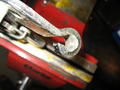 Next up the shoulders of the cable ring end need to removed to allow the ring to pass through the handbrake lever.
 A job easily accomplished with a Dremel, I was surprised at just how good my wife's cordless Dremel is, Ill be borrowing that a bit more I think!
 With those mods made the cable could be assembled to the handbrake lever, and the other end assembled into the handbrake levers at the diff.
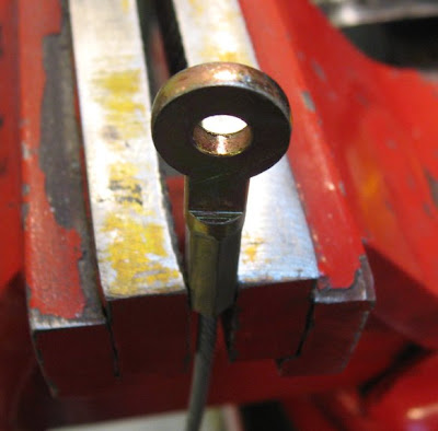
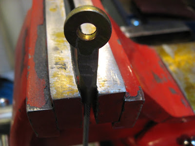
Oh, it was going so well. Whatever I tried I could not get sufficient tension on the cable, with the adjuster nut wound right out there is just enough to apply the brakes. You can still roll the chassis forward though so that's not much use!
This sequence helps explain it. With the nut wound right in and up against the handbrake frame you can see how far the top hat section sticks out the end of the lever. With the top hat pushed home you can see how far the adjuster nut needs to be wound out.
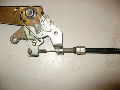 After a call to Simon (cheers mate!) we concluded that there must be something wrong, either the cable inner is too long or the cable outer is too short or a mix of both!
I called Andy at GD and the cable was dispatched on Saturday to them for analysis and replacement.
Watch this space.....
 Next up the shoulders of the cable ring end need to removed to allow the ring to pass through the handbrake lever.
 A job easily accomplished with a Dremel, I was surprised at just how good my wife's cordless Dremel is, Ill be borrowing that a bit more I think!
 With those mods made the cable could be assembled to the handbrake lever, and the other end assembled into the handbrake levers at the diff.
Oh, it was going so well. Whatever I tried I could not get sufficient tension on the cable, with the adjuster nut wound right out there is just enough to apply the brakes. You can still roll the chassis forward though so that's not much use!
This sequence helps explain it. With the nut wound right in and up against the handbrake frame you can see how far the top hat section sticks out the end of the lever. With the top hat pushed home you can see how far the adjuster nut needs to be wound out.


 After a call to Simon (cheers mate!) we concluded that there must be something wrong, either the cable inner is too long or the cable outer is too short or a mix of both!
I called Andy at GD and the cable was dispatched on Saturday to them for analysis and replacement.
Watch this space.....
Sunday 30 March 2008
Fuel line fixed.
Last little job for the day was fixing the fuel line at the rear.
 Done.
Done.
Nothing I can really do now until the engine is run up and the gearbox purchased. Funds building very slowly so maybe a few months before anything else gets ordered.
Dyno booked for 26th April.
Handbrake
Really running out of things to do now so I thought Id have ago at the handbrake.
Didn't cost me much from a local breakers, now where near the £140 new price anyway. Draw back was that it needed a bit of a clean up. It still had the factory part sticker on it!
Didn't cost me much from a local breakers, now where near the £140 new price anyway. Draw back was that it needed a bit of a clean up. It still had the factory part sticker on it!
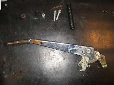
With the grip removed I completely stripped the unit down and cleaned all parts ready for re-assembly, it came up quite well.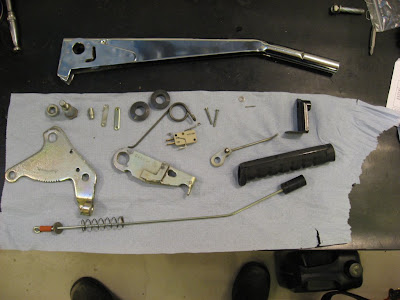 I had thought I would need to replace the pawl release spring (in the handle) as it was very stiff before but luckily after cleaning and lubricating with silicone spray it works well.
The whole thing was reassembled using copper grease, whether this is right or wrong I don't know but I figured it could only help.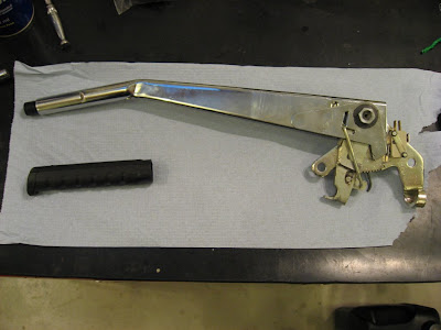 That looks a bit better.
I'm not sure what to do about the grip, I like the clean look of the plain chrome however as it was not intended to be seen its got a couple of notches cut in it. My plastic grip is a bit worn so I could just buy a new one or come up with something a bit different, plenty of time to think about that anyway.
Saturday 29 March 2008
Handbrake springs
With the brake lines in my list of things to do was getting shorter, so next up was fitting the two handbrake return springs.
Shamelessly copying Simon's method I fixed two rivnuts to the chassis, cavity waved the holes and installed the springs.
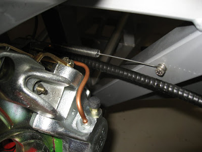 Another job finished.
Do you know the blogger interface really does not like Internet Explorer!
Shamelessly copying Simon's method I fixed two rivnuts to the chassis, cavity waved the holes and installed the springs.
Another job finished.Do you know the blogger interface really does not like Internet Explorer!
Rear Brake pipes conpleted.
With my new roll of pipe, flaring tool and a rough idea of what I wanted to do I set about tackling that little pipe link from the T splitter to the rear calliper.
1st step was to get repeatable results from the flaring tool, I worked out that about 1mm protruding above the tool gave a good result whereas the instructions advised 0.5mm.
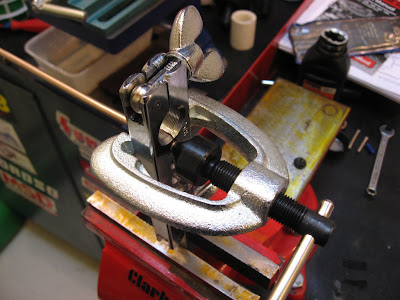
After a few practice runs I settled on using a double flare instead of a single flare. To me it looked more like the GD supplied pipes with their universal flares and it looked to be more robust than the single flare.
With the pipe cut to length and both fittings attached I was able to start bending, well it took three attempts to get a pipe that fitted. Each time I made up a new pipe and had another go.
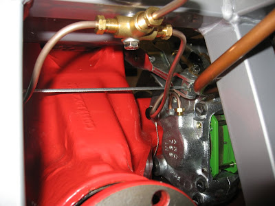
The end result clears the cable and lever well and only time will tell if its routing will cause and problems with bits to be fitted in the future.
What I did notice when doing this is that handbrake levers are lower than those I have seen in other build pictures, this is what caused me the most trouble during this pipe work as I couldn't get a tight enough bend out of the calliper.
Anyway I found that things were not as they seemed, after completing this pipe work I realised that the levers could move up hence increasing the clearance I have achieved in the picture above.
All being well that's that job done.
Friday 28 March 2008
Transmission choice.
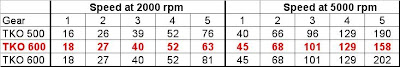
Whilst discussing my brake pipe woes with GD I also raised the which gearbox question. With the wheel and tyre sizes fixed at 18" rims with 275 40's on the back I was able to figure out the transmission ratio that would best suit. Looking at 30mph per 1000 rpm in top I got the following using the TKO600 with the 0.82 5th ratio.
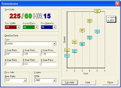 And 5000rpm
 The TKO 500 and 600 with 0.68 & 0.64 5th's respectively gave too short a 1st and a massive theoretical top speed in 5th.
Ill run this by Andy at GD before committing though especially as the TKO 600 is more expensive than the 500.
 And 5000rpm
 The TKO 500 and 600 with 0.68 & 0.64 5th's respectively gave too short a 1st and a massive theoretical top speed in 5th.
Ill run this by Andy at GD before committing though especially as the TKO 600 is more expensive than the 500.
Monday 24 March 2008
Quiet Month
Been a bit of a quiet month in the garage with no real progress.
I set about fitting the two rear calliper feeds from the union, the less said about that the better. Suffice to say I now have a coil of kunifer pipe and a new end fitting on order, at least this way I can now faff about with it as much as I like until I'm really happy with it. This also gives me the opportunity to remake one of the front pipes that I was not happy with.
Left side fitted. Needs to be done again I think as its too close to the cable.
 Right side, kinked it whilst bending! Is knackered.
Had a quick chat to someone at GD, didn't get his name that's not too good! Anyway was advised to use a 1" mandrel to make the initial bend out of the calliper, that should stop the pipe collapsing.
New roll of pipe and new fitting arrived so ready to give it a go this weekend.
Sunday 10 February 2008
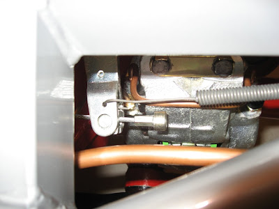
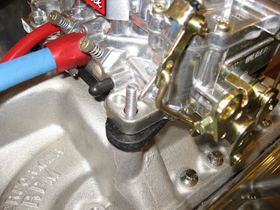
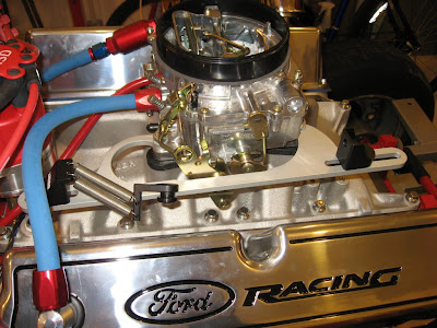
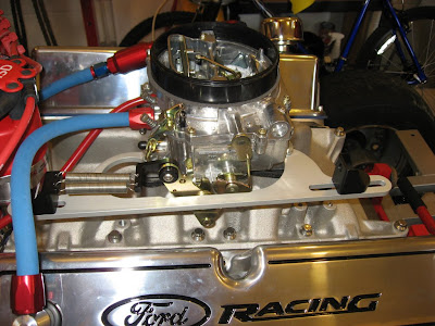
Throttle Bracket & Return Springs.
After looking around for a solution for the throttle return springs I eventually wound up at Jegs. So one internet order later I an the happy owner of a Jegs throttle bracket with return springs.
Ordered it on Tuesday, arrived on Thursday. Cost $78 delivery buts that's quick! (Jegs only ship by FedEx which is not the cheapest)
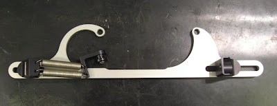 Step 1.
Remove existing studs and replace with 2" ones. Ive only changed the two on the side of the bracket.
 Step 2.
Fit bracket and tighten nuts.
 Step 3.
Fit return spring attachment to carb linkage.
Job done until I get the throttle cable and sort the end out.
Ordered it on Tuesday, arrived on Thursday. Cost $78 delivery buts that's quick! (Jegs only ship by FedEx which is not the cheapest)
 Step 1.
Remove existing studs and replace with 2" ones. Ive only changed the two on the side of the bracket.
 Step 2.
Fit bracket and tighten nuts.
 Step 3.
Fit return spring attachment to carb linkage.

Job done until I get the throttle cable and sort the end out.
Subscribe to:
Posts (Atom)