Saturday 22 December 2007

Sparky time.

With fuel sorted and the carb to mix in the air the final bit needed for the bang is the ignition wires (this isn't a diesel!).

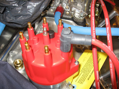
Having already laid them in to find the right wire for each pot I set about fitting the ends.

The sequence is this:

1. Cut to length.
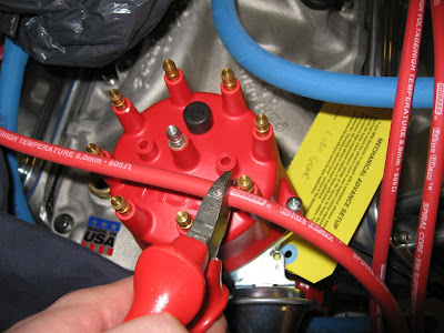
2. Use strip tool supplied to strip insulation away.

Clever tool this, you just twist it until 9mm of wire pokes out the end, then grip the wire to stop it going through to toll and twist a couple more turns. Pull and off come the insulation.
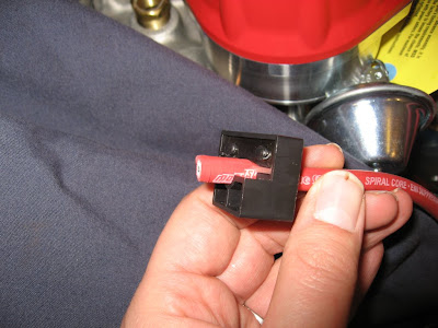
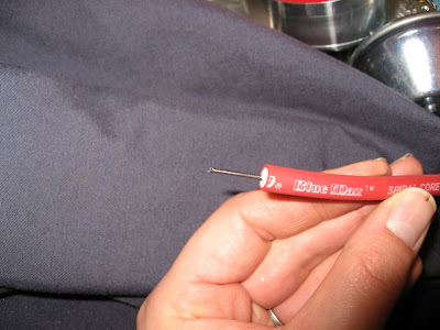
3. Fold over core and crimp on terminal. (Fold down terminal ears with long nose pliers)

4. Apply silicone lube and slip on boot.
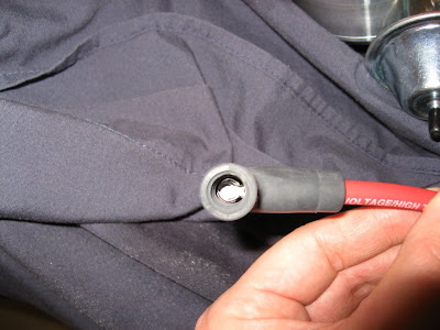
5. Fit to distributor cap.

6. Repeat for all remaining leads.


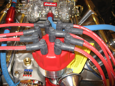
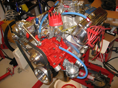
7. Apply air cleaner with Ford wing nut and stand back to admire tidy wire layout on nearly finished engine.
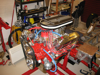

This however is where it went a bit wrong.

Whilst fixing the wires I followed good old Tom's book, what I didn't check was what I was doing!
I followed the instructions for the HEI ignition module used by Ford, this does not connect the wires in the firing order as the dizzy rotor turns, therefore my firing order is now wrong!

Thinking about it logically I would have realised that something was not right but I was too eager to get it finished, in future I need to think a bit more first!

Luckily for me Ive only had to move four wires around but it has mucked up my tidy layout, still cant be helped. (picture to follow).
Engine Fuel system.

With a final push the engine is now nearly completed.

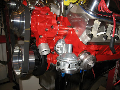
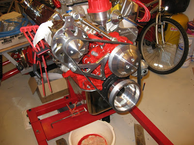
First off the fitted drive belt looks nice, I prefer the appearance of the poly-V belt over the standard V belt setup. Just looks more chunky!


Next I fitted the fuel pump, here you can see the block off in the bottom holes as I checked they fitted in all four of the outlet holes.

With the blocks offs moved to the side ports, JIC adapters fitted to the inlet & outlet, sealant on both gasket faces and assembly lube on the arm, I installed the pump to the block with a little persuasion.

Now I can connect the fuel lines without interfering with the oil filter take off or water hose.

Next I turned to the fuel lines to complete this side of the job.

After thinking about it I decided to install a filter in the engine bay as well as the boot, this gives double protection and means that the engine is protected when it goes to the dyno. A suitable Summit filter was obtained, with removable element, in a nice red colour of course!

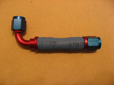
The Aeroquip hose is a "simple" push fit, I say "simple" as its Bl$$dy hard!

1. Measure and cut hose.
2. Choose correct fitting. (fell down here as I fitted two 90° bends first out!!)
3. Lube inside of hose with oil.
4. Push fitting into hose until it bottoms out on the flange.
5. Try to pull hose off (no chance!)

Anyway the link to the in line filter was done with much swearing (the scar has only just faded on my palm!)


Same exercise was carried out once the filter was fitted from the filter to the fuel pump. Following images I have seen from other engine builds I routed my fuel pump under the water neck to keep things tidy. Time will tell if this is a problem but I don't think the water neck is going to exceed the 150°C rating of the hose.


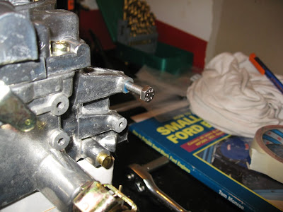
Whilst fiddling with the fuel lines I remembered the choke on the carb. I don't plan to use the choke but have decided not to remove its parts. So as compromise I will hold it open with a spring. To do this I need somewhere to hook said spring.

I located a suitable drilling on the carb, taped it and added a bolt. Done.

With a spring from the brass colour lever you can just see on the left of this picture to the bolt my choke should remain open.

That's it for today.