Up the front the Jag lower arm was readied for installation, I trial fitted the lower pivot shaft and found that, as was stated in the GD build notes, my new shaft was slightly over on OD due to the plating. With the shaft clamped in my press it was the work of a few minutes to reduce the OD with a bit of abrasive pad.
The chassis tube and pivot shaft was well greased, the lower wishbone was offered up to the chassis and persuaded to fit with the thrust washers between the chassis and bushes in the lower arm.
With the shaft knocked through (not all the way or you wont get the nut on!) I could fit the washer and nut and tap through to complete. The nut was tightened and the split pin inserted and bent to lock the nut in place. It does not matter with the powerflex bushes where the lower arm is when the nut is tightened but if you are using direct replacement Jag bushes the lower arm must be horizontal to prevent the bushes from tearing.
 With the lower arm in place The upper arm came next. A small issue was found here, as assembled the pivot bracket would not fit to the chassis. The inner thrust washer was fouling on the mounting plate. So I disassembled both sides and swapped the pivot shafts over and eventually I managed to get a combination that would fit without having to take a file to the chassis!
With a pair of new bolts (not supplied in the GD bolt kit!) and additional washers front and back I bolted up the top pivot shaft, note the main pivot shaft nyloc's are left loose at this stage.

 I'm not sure I have enough thread protrusion on the rear of these bolts for Mr SVA, only time will tell.
Next I fitted the shock unit, you can leave this out if you are going to set your geometry now but as I have a bit of time before I come to that task I decided to fit the shock such that the front assy. was self supporting.
Simple really, just use two bolts, two nuts and 4 washers.
 To finish off this side the final bit to fit was the upright assembly. This is a heavy part to lift into place and fiddle around locating ball joints!
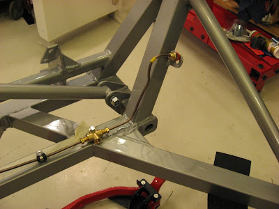
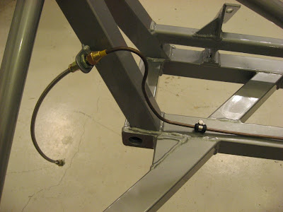
From the back..

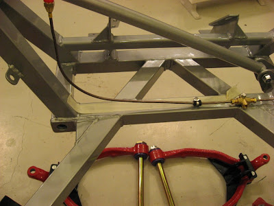
And a closer shot of the front..
 One point of note, it is not possible to get a socket and torque wrench on to the bottom ball joint nut once the top ball joint is located. Well not with my torque wrench anyway!
The same sequence was repeated on the other side except I tightened the lower ball joint nut before I located the upper joint into the upright. Took a bit of balancing of the hub on my jack, oh and a support strap in case it slipped off the jack, but the job was done.

Next up the steering rack.....