I neglected to mention that whilst the block was away at South Cerney I also had the rotating assembly balanced at Bassett Down Balancing. Again this company came to me by recommendation.
The crank, rods, flywheel, flywheel bolts, pistons, balancer and one each of the main and rod bearings all went off to Bassett Down. Here I again felt the pain of not buying bits in the correct manner. The crank turned out to be for a 50oz balance whereas the flywheel and balancer were for 28oz. So to sum up a lot of machining work was done to bring it all to 50oz balance, lots of work unfortunately meant lots of money. I now really wish I had purchased a complete rotating assembly as a kit.
Back to engine assembly.
I turned my attention to completing the rotating assembly. The rods I had purchased were for press fit pins, a money saving tip would have been to buy floating pin rods so that I could have fitted the pistons myself. Instead I paid South Cerney to fit the pistons onto the rods for me.
Rings
The rings required gapping so I shelled out for a ring grinder from Summit.
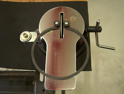
Well worth the money but now surplus to requirements. May go on ebay once the motors up and running!
A good tip here is to get a ring board setup, basically 16 screws in a piece of board number 1 – 8 twice. The top and second rings then go on these once gapped correctly. This way, as each ring is gapped to a particular cylinder, it is easy to keep them organised. However don’t do what I did and get confused as to which cylinder is #1!
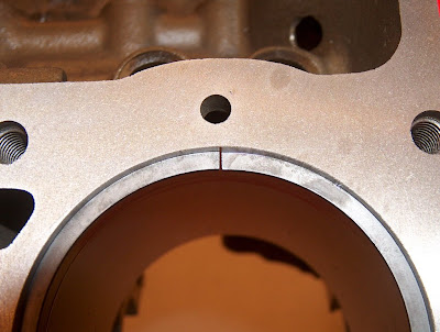
Each ring was placed into its cylinder and the gap measured, the KB115 piston’s are Hypereutectic and as such run a higher temperature in the cylinder. This causes the top ring to expand and, if not gapped correctly they will but up against each other causing the top ring land to break.
KB state the top ring gap should be 0.0065” for each 1” of bore so 4.030x0.0065 gave me 0.026” of gap, which looks like this:
A good tip here is to get a ring board setup, basically 16 screws in a piece of board number 1 – 8 twice. The top and second rings then go on these once gapped correctly. This way, as each ring is gapped to a particular cylinder, it is easy to keep them organised. However don’t do what I did and get confused as to which cylinder is #1!
Each ring was placed into its cylinder and the gap measured, the KB115 piston’s are Hypereutectic and as such run a higher temperature in the cylinder. This causes the top ring to expand and, if not gapped correctly they will but up against each other causing the top ring land to break.
KB state the top ring gap should be 0.0065” for each 1” of bore so 4.030x0.0065 gave me 0.026” of gap, which looks like this:
 With the rings gapped and hung on the board I was ready to start fitting them to the pistons. Again each piston was numbered 1-8 and the associated ring set applied for that piston.
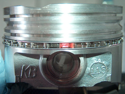
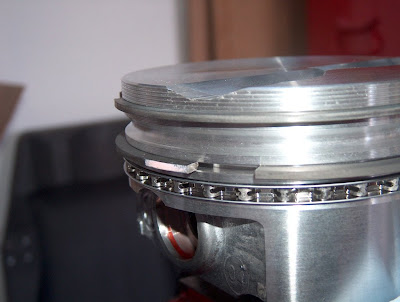
The oil rings went on first, first the lower oil ring then the expander and then the top oil ring, the expander has two small pieces of coloured plastic in the end sections to prevent the ring from overlapping itself, when fitted correctly it should look like this.
Next comes the 2nd rings and then the top rings, each of the top rings was identified by a chamfer to the inner edge of the ring and must be placed on the piston the correct way up, a helpful dot etched into the ring tells you which way up.
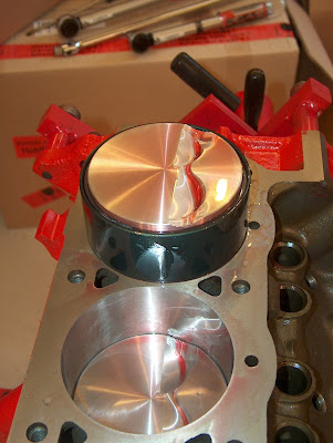
With all eight pistons ready to install it was time to go for it and fill the cylinders up. Here again I thought it best to get the best tool for the job so I purchased a 4.030 diameter fixed ring compressor from Real Steel. This tool is sized exactly to the bore and has a reducing inner diameter from top to bottom. As the tool is flat bottomed it fits flush to the deck surface, so as long as you keep the tool pressed down the piston should just slide right in, in theory!
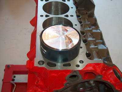
Well the theory was good and actually in practice not much different, the only issue I found was that the slope of the engine on the stand caused the rod to slide on the piston pin to the back face of the piston. This then caused the big end to foul on the crank as the piston was tapped home. Not a problem if you are working as a pair but with only two hands it was not possible to hold the rod away from the crank counterweight at the same time as tapping the piston and holding the compressor against the block.
I solved the problem by lifting the rear of the engine stand up so it was level, the rods no long slid and all was well.
Each piston was loaded and the cap loosely fitted, within a relatively short space of time the last piston was going in.